Specific Issues
FIR filters
FIR decimation filters are sometimes left out of StationXML files because they generally have unity gain and a flat frequency response to near the Nyquist frequency. However, the last FIR stage in a decimation can have an important effect on signals near or above the Nyquist frequency. The figure below, from [Scherbaum1997], shows the effect of a zero-phase FIR decimation filter on a P-wave arrival.
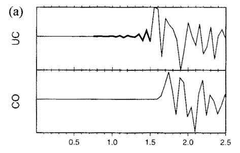
Earthquake P-wave arrival on a land station: (top) original data recorded with a zero-phase FIR decimation filter; (bottom) the data transformed to the equivalent minimum-phase decimation filter.
We have seen the same problem in higher-frequency data from a local earthquake network.
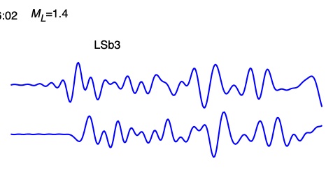
Small-magnitude local P-wave arrival on an OBS at Lucky Strike volcano (from [Crawford2013]). Top: original zero-phase filtered data. Bottom: minimum-phase corrected version .
This artifact is significant if the arrival is impulsive and has energy near to or above half the sampling rate (the Nyquist frequency). The artifact exists because signal before the impulse peak is a necessary side-effect of the zero-phase requirement. Dataloggers create zero-phase filters by convolving data with a symmetric “linear phase” filter, then shifting the time tag to correspond to the offset of the central peak of the filter.
A “minimum phase” FIR filter is the causal filter with minimum offset from the original impulse peak. [Scherbaum1997] showed that zero-phase filtered data could be converted to “equivalent minimum phase” filtered data, if the original zero-phase filter coefficients are known.
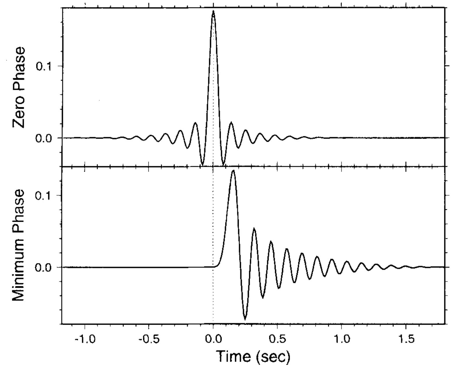
Equivalent zero-phase (top) and minimum-phase (bottom) filters. The vertical dotted line indicates the impulse arrival time.
Based on this example, one might think that minimum-phase decimation filters are better than zero-phase filters for seismology data. They are better for phase arrival picking, but zero phase filters provide less-biased inputs for full waveform modeling and inversions. Therefore, it is always useful to include the last FIR decimation stage, to allow post-recording conversion from one filter response to the other.
It is also generally useful to specify the preceding FIR decimation stages as well. They generally have much less effect on the causality if the signal, but their frequency response can be necessary to construct an accurate overall instrument response. For example, “intermediate” FIRs sometimes have many fewer coefficients than the final FIR stage. This is done to reduce processing power as well as digital delay, but it also means that the instrument response can not be as finely tuned as in the last stage. For example, the FIR2 stages of a CS5322 digital filters have only 13 coefficients (compared to 101 in the FIR3 stage), so their frequency response drops off gradually towards higher frequencies rather than being constant out to near the Nyquist. To compensate for this, the FIR3 stage has a response peak near it’s Nyquist. When the FIR2s and FIR3s are multiplied together, the result is a flat response out to near the Nyquist, but if the FIR2s were not included in the StationXML file it would appear as if there were a peak in the frequency response just below the Nyquist.
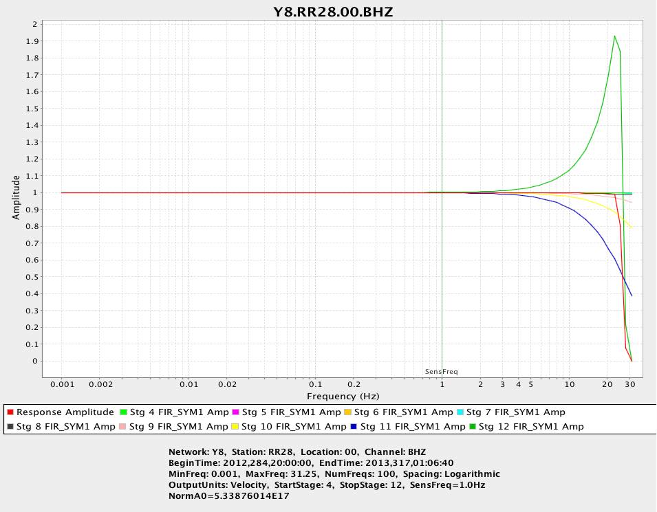
Frequency response of CS5322 FIR filters: green = last FIR stage, blue = previous FIR stage, red = overall response.
Filter delays
Linear-phase filters can significantly delay the signal.
For example, the linear-phase filter in the last FIR stage of a Cirrus Logic
CS5322 Digital Filter has 101 coefficients,
meaning that the peak is 50 samples after the
first coefficient.
After the following divide-by-two decimation, the signal is therefore delayed
by 25 samples.
The previous FIR stages can add to this delay: in the case of the
Cirrus Logic CS532 filter, the previous stages add 4 more samples of delay,
for a total of 29.
A zero-phase output is obtained by shifting the time tag 29 samples EARLIER
than the data recording time, in the recording software.
This is the correction.`
You can verify if your system applies the right correction by inputing a GPS PPM on one of your instrument channels.
If the software does not apply this correction, data will be time tagged 29
samples too late.
This is nearly invisible, but not necessarily unimportant, in a network
composed of one make/model of instrumentation: if the source is an
earthquake then its origin time will be shifted by 29 samples; if the source
origin time is known (e.g., “controlled” sources like airguns or explosives),
then the velocity model fitting the data will have to be slightly slower
than reality.
If different types of instruments are used then there may be significant
inconsistencies between arrival times.
So, instrumentation software should always correct for time delays.
If this is not the case, one must correctly specify the FIR delays and the
lack of correction, although not all picking/processing software looks/corrects
for a discrepancies between delay and correction.
obsinfo_ automatically calculates the time delay due to the FIR filter stages,
for which you specify delay.samples.
You should also provide the correction applied to the data by the datalogger,
even if it is 0.
For compatibility with other systems, if you do not indicate the correction,
obsinfo_ will assume perfect correction, setting each stage’s correction equal
to its delay.
If you do set correction, obsinfo_ will set correction=0 for all
stages except the last, in which it will place the correction value
you provided.
Scherbaum F. and M.-P. Bouin (1997), FIR filter effects and nucleation phases, Geophys. J. Int., 130(3), 661-668
Crawford et al. (2013), Hydrothermal seismicity beneath the summit of Lucky Strike volcano, Mid-Atlantic Ridge, Earth Plan. Sci. Lett., 373, 118-128, doi:10.1016/j.epsl.2013.04.028.