Building a stage_base file
Stages are the building blocks of instrument responses. Each instrument component of an instrumentation channel consists of at least on stage. stages are always specified as lists of stage objects, with the topmost object being applied first.
Note: since stages are chained, the output units of a stage must match the input units of the next stage.
Digital stages
In StationXML, each digital stage has an input and an output sample rate. In reality, most digital stages have no fixed sampling rate, they just apply their coefficients and decimation to the output from the stage above. In obsinfo, therefore, only the top-level digital stage (usually the delta-sigma input) should have a specified frequency: the final output sampling rate will depend on the decimations introduced by the subsequent digital filter stages. obsinfo checks that the declared sample rate of the instrument matches the calculated sample rate of the list of stages.
Every stage has an associated filter. obsinfo allows simplified filter
specifications for stages that have no filter, as we will see in the next
tutorial section.
Template stage_base file
The template stage_base file uses a pole-zero filter:
> obsinfo template stage_base
---
format_version: "1.0"
revision:
   authors:
        - {$ref: "persons/EXAMPLE.person.yaml"} # Reference to person file,
                                                 # or fields of a person element
   date: "2024-09-30" # yyyy-mm-dd
stage_base:
    input_units:
        name: "V"
        # BEGIN OPTIONAL units elements
        description: "Volts"
        # END OPTIONAL units elements
    output_units:
        name: "V"
        # BEGIN OPTIONAL units elements
        description: "Volts"
        # END OPTIONAL units elements
    gain :
      value: 10     # Gain (output_units/input_units)
      frequency: 10 # Frequency at which gain is given
    filter: {$ref: 'sensor_bases/stage_bases/filters/EXAMPLE_BBSeismometer_SN1-399.filter.yaml'}
    # BEGIN OPTIONAL stage_base elements
    name: "Funky filter"  # Stage/Filter name
    description:  "Oddball offbeat filter"  # Stage/Filter description
    delay: 0  # Value to put in StationXML stage w/o modification.
             # if not specified and this is a digital stage, calculate
             # as filter offset / input_sample_rate
    polarity: "+"  # "+" if the stage does not invert sign from input to output
                  # "-" if it does invert sign
                  # ("+")
    input_sample_rate: 100  # Only use if fixed input_sample rate
    decimation_factor: 2  # Factor by which this stage decimates data
    calibration_dates:
        - "2004-12-31T00:00:00"
        - "2024-12-31T00:00:00"
    resource_id: "IPGP:2004iepw44" # Unique ID of the filter, typically
                                   # "GENERATOR:Meaningful_ID"
    configuration_default: "10x"
    configurations:
        "1x": {gain:  {value : 1, frequency : 10.}}
        "5x": {gain:  {value : 5, frequency : 10.}}
        "10x": {gain:  {value : 10, frequency : 10.}}
        "20x": {gain:  {value : 20, frequency : 10.}}
    # END OPTIONAL stage_base elements
# BEGIN OPTIONAL top-level elements
notes:
   - ""
# END OPTIONAL top-level elements
It validates with obsinfo schema and prints with obsinfo print:
TEMPLATE.stage_base.yaml:
    Stage:
        name: Funky filter [config: 10x]
        description: Oddball offbeat filter
        input_units: V
        output_units: V
        gain: 10
        gain_frequency: 10
        filter: PolesZeros
            stage_id: #-1 ("Funky filter [config: 10x]")
            11 poles, 6 zeros
            transfer_function_type: LAPLACE (RADIANS/SECOND)
            normalization_frequency: 10
            normalization_factor: 4.546e+17
        calibration_dates: OIDates:
            - 2004-12-31T00:00:00
            - 2024-12-31T00:00:00
        input_units_description: Volts
        output_units_description: Volts
        input_sample_rate: 100
        decimation_factor: 2
        decimation_offset: 0
        delay: 0
        correction: None
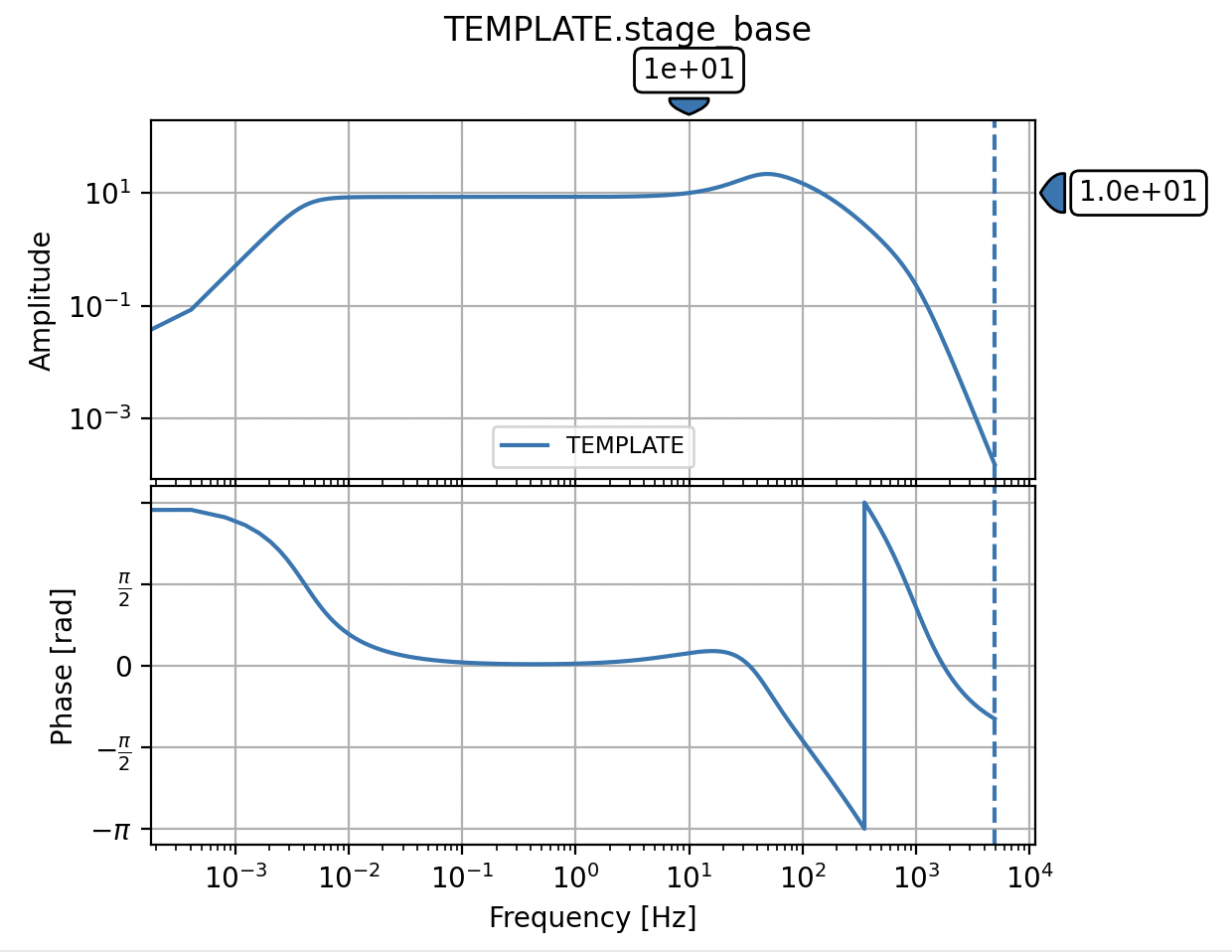
obsinfo plot reveals that this is probably a broadband seismometer stage,
with a flat gain between about 100Hz and 200 seconds: